


What is Electrical Resistance
As its name implies, an electric resistor is an electronic component that resists the flow of electric current in a circuit. Electric resistors are divided into two different types of materials, conductors and insulators. The conductor allows the flow of electric current whereas an insulator does not. So the conductor materials should need the electric resistor components in their structure. Every electrical equipment has an internal circuit the working of this circuit primarily depends on the proper input voltage, grounding connections, and dissipated heat should be minimum. From all these one of the important points to be considered, there is electrical circuit resistance. In any circuit design, the electric resistor plays a key role by helping the electrical circuit to maintain the proper voltage and electric current.
What is Electrical Resistance?
A resistor is a two-terminal electrical component. The primary property of a resistor is to resist the electrical flow or reduce the electric current flow. They help to adjust current and voltage in an electrical circuit, just like a faucet helps to adjust the tap water flow. In addition to adjusting the current flow in the electric circuit, resistors also allow voltage distribution. The surplus electric current is transformed into heat when the current is reduced in an electrical circuit using a resistor. There are three types of resistors, fixed resistors, variable resistors, and potentiometers.
Ohm’s Law
A German scientist George Simon Ohm proposed a theorem that shows the relation between voltage, current, and resistance in an electrical circuit. By this theorem, we can find out how much resistance value is needed for an electric circuit with the known value of voltage and current. We can also find the values of voltage, resistance, and current by the theorem of Ohm’s law. Ohm’s law states that the electric current through a conducting material/device between ranges is directly proportional to the voltage across the same range. That is to say, the created current through a conducting device is directly proportional to its input voltage. The resistance formula is V = I x R.
PCB Way
From above ohm’s law, we can find the current and resistance value also.
I = V/R
R = V/I
Electric Resistor
Inside an electric resistor – if you break and open any one side of the resistor-colored strip point, you can observe an insulated copper rod that is covered with copper wire around it. The count of copper wire turns can be decided by the value of resistance. If the resistor has many coppers turns in a thin form then such resistors have higher resistance. If the resistor has a few copper turns then such structured resistors have a lower resistance value. These lower resistance valued resistors are suitable for the mini circuit or smaller applications or devices.
How Does a Resistor Work?
A resistor introduces resistance into an electrical circuit, which can help to control the electric current and voltage flow. By controlling the flow of electricity, they can help to adjust the voltage and current in the electric circuit. Some types of resistors, like metals, allow electrons to flow freely, which is why they make good conductors. In contrast, others, such as rubber or glass, are more resistant. That is what makes them good insulators. In a typical electrical circuit, current flows from the positive terminal of a power source through the resistor and back to the negative terminal. As you can see, it acts like a roadblock in the electric circuit, forcing the electrical current to slow down. Additionally, if the resistance is too large, it will not provide suitable resistance to the electric current, which may result in overheating. Conversely, if the resistance is too small, it will create too much of current, and the current may not flow at all.
The Size of the electric Resistor Affects the Electrical Resistance Value
The size of the electrical resistor can decide the resistance value. George Ohm also demonstrates a relationship between the length and the material of the resistor (from which material the resistor was made). The equation is R = ρ x L / A (R = Resistance, Ρ = Resistivity of the material, L = Length, A = Area).
As far as we know, these materials are classified into two types. They are conductors and insulators. In conductive materials, the length plays a significant role while maintaining the electric resistance value. In conductive material, if the length of the wire is too long then it has a large number of free electrons in it. So when these electrons got sufficient input voltage, they will get enough kinetic energy. And these electrons get collision with other positive ions.
Therefore, longer conductors provide more resistance than shorter conductors/wires. If the length of the wire increases, then its resistance also increases as we mentioned above. But if the area of the material increases, the electrical resistance is decreased. Here the resistance and area of the material are inversely proportional to each other. Additionally, the type of material can also violate the resistance value. Such as the temperature can able to change the resistance value.
Variation in Resistance with Increase in Temperature
What would happen to the electric resistance of pure metal when you increase its temperatures? An increase in temperature will increase the electric resistance of pure metals. This change in resistance happens because of an increase in the number of electrons in the conduction band and an increase in the atomic vibration within the wire, which causes reducing the mobility.
What would happen to the electric resistance of pure metal when you increase its temperatures? An increase in temperature will increase the electric resistance of pure metals. This change in resistance happens because of an increase in the number of electrons in the conduction band and an increase in the atomic vibration within the wire, which causes reducing the mobility.
So, what would happen to the electric resistance of an insulator if you increase its temperature? The opposite scenario takes place when you raise the temperatures of an insulator. Its resistance decreases. The reason why is that this change is the increased electron movement from the conduction band to the valence band because the energy gap is large between these two bands. Therefore, the resistance decreases as conductance increases.
What would happen to a circuit if there were no resistance?
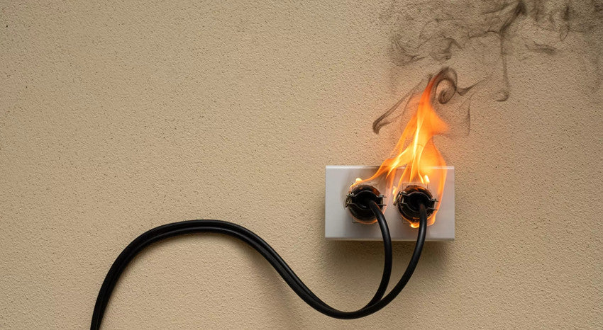
Typically, the electric current will flow in the correct way as long as it has a path with finite resistance (even zero), a voltage difference, and a supply of electric charge (e.g., electrons). If there were no resistance in the electric circuit, the electrons will go around the circuit, and return back to the beginning of the electric circuit with as much energy as the potential difference (the voltage). The final energy will be dissipated as heat or other types of energy by the circuit. That is to say, if there were no resistance in the electric circuit (or inductance) it will not have a chance to lose the energy, and it will return to the voltage source with lots of energy, which will typically screw up the voltage source or catch fire. This is essentially a short circuit.
Resistance and Reactance
Mathematically, resistors prevent electric current from flowing, they have the property of resistance. Electrical resistors are found in both alternating current and direct current circuits, and the energy that is prevented from flowing is expelled as heat. Mathematically, electric resistance is simply voltage divided by current (R = V/I).
Electrical reactance is a property that resists a change in the electric current and is found in both inductors and capacitors. Because it only affects changing current, electrical reactance is specific to alternating current power and depends on the frequency of the electric current. When the electrical reactance is present, it creates a 90-degree phase shift between voltage and current, with the direction of the shift depending on whether the component is an inductor or a capacitor. The electric reactance that occurs in an inductor is called inductive reactance. When the inductive reactance is present, the energy is stored in the form of a changing magnetic field, and the electric current waveform lags the voltage waveform by 90 degrees. Inductive reactance is caused by devices such as coils (including line reactors), chokes, and transformers where wires are wound in a circle. Additionally, the electric reactance that occurs in a capacitor is called capacitive reactance. The capacitive reactance stores the energy in the form of a changing electrical field and causes the current to lead the voltage by 90 degrees. Capacitance is produced when two conducting plates are placed parallel to each other with a small distance between them and filled with a dielectric material (insulator).
How is Resistance Different from Reactance?
There are several similarities between reactance and resistance. For example, both oppose the electric current flow and have the same unit which is Ohms (Ω).
However, the electric reactance creates only when there is a change of current in capacitors and inductors, as it depends on the frequency of the Alternating Current passing through the capacitor or the inductor. While resistance is an obstruction to the current flow, that is, it opposes electron flow and makes them slow.
How to Calculate Total Resistance in Circuits?
Electrical components are connected in either of two methods:
Series circuit: electric components are connected one after the other.
Parallel circuit: electric components are connected along parallel branches.
Calculating Total Resistance in a Series Circuit
In a series circuit, the total resistance can be calculated by adding the resistances of all the components. For example, series circuits have these resistors, a 6 Ω, a 5 Ω, and an 8 Ω resistor. The total resistance in a series circuit is given by R1 + R2 + R3
R = 6 + 5 + 8
R = 19 Ω
If you are not given the individual resistance values, you can use Ohm’s law to calculate the resistance using the formula: V = IR. Remember that the electric current in a series circuit is the same at all points. The total voltage is the same as the voltage of the supply. Using the electric current and the voltage, you can find the total resistance in the circuit and then calculate the individual resistances.
Calculating Total Resistance in a Parallel Circuit
A circuit that branches into multiple paths and is connected in parallel is known as a parallel circuit. When the electric current flows through each branch of the parallel circuit, the total resistance can be calculated by using this formula: Total resistance = 1R1+1R2+1R3.
For example, if a parallel circuit has four branches with resistances of 10 Ω, 2 Ω, 5Ω, and 1 Ω, the total resistance can be calculated as this formula: R = 110+12+15+11
R = 1+5+2+1010
R= 1810
R= 1.8 Ω
If you do not know the individual resistance, you can use Ohm’s law to find resistance. However, remember that the voltage across a branch in a parallel circuit is the same as the total voltage across the circuit. The electric current can be different in each branch, so you must know the total current. Using the total current and voltage across the circuit, you can calculate the total resistance in the circuit and then find individual resistances.
Examples of Resistance in Everyday Life
The electrical resistance and Ohm’s law can be observed in everyday life. There are some examples of electrical resistance below.
Conventional Domestic Fans
The electric fan's speed is controlled by the regulator. It is possible to check the electrical current flowing through the fan by using a regulator to alter the resistance. The circular knob rotation helps attain variable resistance across the output terminals.
Electric Heaters
The electrical heaters have metal coils that have high resistance. It allows only a limited amount of electric current through it and gets heated up in the process. You can easily calculate the power needed to be supplied to the heater by using Ohm’s law.
Electric Irons and Kettles
Electric kettles and irons have multiple resistors that limit the amount of electric current passing through them to provide the needed heat. The size of the resistor can be determined by using Ohm’s law.

Fuse
Electric fuses are protective components that are playing an important role in limiting the amount of electrical current flowing through household circuits. The electric wires inside the fuse have high resistance and low melting point. The high resistance prevents an electric current higher than the prescribed value from passing through it, while the low melting point permits it to break the circuit when a high current flows through it.
Conclusion
Electrical resistance may seem like a negative word, but it plays a huge role in electrical circuits. This is analogous to friction. A higher resistance creates a greater hindrance in the electric current flow path, while a lower resistance allows easier flow. This concept is the basis of many electrical appliances and makes various technologies possible.


